
Page 119 - Gaylord Blue Book 2021
P. 119
Specifications (Continued) 2.2.12 Agent Distribution Hose: Kitchen appliances manu-
factured with or resting on casters (wheels/rollers)
2.2.4 Tank Valve: The tank valve shall be designed which have the fire suppression system hard piped,
to discharge dual agent onto the hazards being shall include a UL Listed agent distribution hose
protected. The valve shall automatically shuttle to as a component of the suppression system. This
switch from wet chemical agent discharge to water option shall allow the appliance to be moved for
discharge. cleaning purposes without disconnecting the appli-
2.2.5 Regulated Release Mechanism: The regulated release ance fire suppression protection. Hose assembly
mechanism shall be a spring-loaded, mechanical/ shall include a restraining cable kit to limit the
pneu matic type capable of providing the expellant appliance movement within the range (length) of
gas supply via a pressurized cartridge to a single the flexible hose.
agent tank. It shall contain a factory installed regulator 2.2.13 Flexible Conduit: The manufacturer supplying the
deadset at 150 psi (10.3 bar) with an internal relief of restaurant fire suppression system shall offer flex-
approximately 190 psi (13.1 bar). ible conduit as an option to rigid EMT conduit for
It shall have automatic actuation by a fusible link the installation of pull stations and/or mechanical
or electric detection system and remote manual gas valves. The flexible conduit shall be UL Listed
actuation by a mechanical pull station. and include all approved components for proper
installation.
The regulated release mechanism shall contain a
release assembly, regulator, expellant gas hose, 2.2.14 Pull Station Assembly: The fire suppression system
anti-siphon vacuum breaker, and agent storage tank shall include a remote pull station for manual
housed in a stainless steel enclosure with cover. The system actuation. The pull station shall include a
enclosure shall contain knock-outs for 1/2 in. conduit. built-in guard to protect the pull handle. The pull
The cover shall contain an opening for a visual status station shall also be designed with a pull handle to
indicator. allow for three finger operation and shall be red in
color for quick visibility.
It shall be compatible with mechanical gas shut-off
devices or, when equipped with a field or factory-
installed switch, compatible with electric gas line or
appliance shut-off devices.
2.2.6 Discharge Nozzles: Four types of discharge nozzles
shall be tested and listed with the system for all
applications. Discharge Nozzles are available for low,
medium, or high proximity applications. When using
high proximity nozzles, nozzle drop piping can be kept
to a minimum. In some applications, nozzles may be
installed above the cooking appliance line directly in
hood seals penetrating top of the hood. The P34 and
P41 types shall be used for high proximity appliance
protection, nozzle height ranges from 54 in.(1,371 mm)
to 84 in. (2,133 mm). The AP type shall be used for
medium proximity appliance and plenum protection,
nozzle height ranges from 40 in. (1,016 mm) to 48 in.
(1,219 mm), and the DL type shall be used for all duct
and low proximity appliance protection, nozzle height
ranges from 13 in. (330 mm) to 24 in. (610 mm). Each
nozzle shall have a metal blow-off cap to keep the 009601
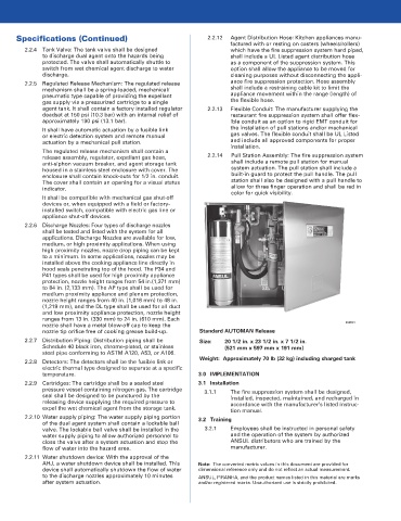
nozzle tip orifice free of cooking grease build-up. Standard AUTOMAN Release
2.2.7 Distribution Piping: Distribution piping shall be Size: 20 1/2 in. x 23 1/2 in. x 7 1/2 in.
Schedule 40 black iron, chrome-plated, or stainless (521 mm x 597 mm x 191 mm)
steel pipe conforming to ASTM A120, A53, or A106.
Weight: Approximately 70 lb (32 kg) including charged tank
2.2.8 Detectors: The detectors shall be the fusible link or
electric thermal type designed to separate at a specific
temperature. 3.0 IMPLEMENTATION
2.2.9 Cartridges: The cartridge shall be a sealed steel 3.1 Installation
pressure vessel containing nitrogen gas. The cartridge 3.1.1 The fire suppression system shall be designed,
seal shall be designed to be punctured by the installed, inspected, maintained, and recharged in
releasing device supplying the required pressure to accordance with the manufacturer’s listed instruc-
expel the wet chemical agent from the storage tank. tion manual.
2.2.10 Water supply piping: The water supply piping portion 3.2 Training
of the dual agent system shall contain a lockable ball
valve. The lockable ball valve shall be installed in the 3.2.1 Employees shall be instructed in personal safety
water supply piping to allow authorized personnel to and the operation of the system by authorized
close the valve after a system actuation and stop the ANSUL distributors who are trained by the
flow of water into the hazard area. manufacturer.
2.2.11 Water shutdown device: With the approval of the
AHJ, a water shutdown device shall be installed. This Note: The converted metric values in this document are provided for
device shall automatically shutdown the flow of water dimensional reference only and do not reflect an actual measurement.
to the discharge nozzles approximately 10 minutes ANSUL, PIRANHA, and the product names listed in this material are marks
after system actuation. and/or registered marks. Unauthorized use is strictly prohibited.