
Page 81 - Gaylord Blue Book 2021
P. 81
DCV-AVND AirVantage
ITEM NO. _______________
MODEL “DCV-AVND”
DEMAND CONTROL VENTILATION
WITH SMART READ AND REACT TECHNOLOGY
MULTIPLE HOOD MULTIPLE FAN EXHAUST SYSTEM
GENERAL SPECIFICATIONS AND DESCRIPTION
Furnish Gaylord Demand Control Ventilation (DCV) with smart read and
react technology Model “DCV-AVND” (AirVantage No Damper) as shown 6
on plans and in accordance with the following specifications:
DCV-AVND SYSTEM DESCRIPTION: The purpose of the DCV-AVND
(AirVantage No Damper) system is to reduce kitchen operational and 6 6
utility costs by conserving energy through the reduction of exhaust and 3
makeup air for the commercial kitchen ventilation (CKV) system while 5 5 5 HCE
effectively communicating with the Building Management System (BMS). 5
RTD RTD RTD 4 RTD
2 VFD
DEMAND CONTROL VENTILATION (DCV-AVND) SYSTEM:
1
• Shall have an AirVantage Command Center enclosure including: 7-inch x
4.3-inch color touchscreen HMI digital control, room ambient temperature 4
sensor, fire suppression integration controls, and VFD/BMS/VAV interface Override Button
terminals.
• The AirVantage Command Center housing shall be constructed of 300
series stainless steel with a #4 finish complying with NSF/ANSI 2-2010.
• Shall utilize listed, programmable stainless steel resistance temperature AirVantage
detectors (RTDs) mounted inside the hood canopy to accurately read Command
sensible heat from the cooking equipment and vary the speed of the Center
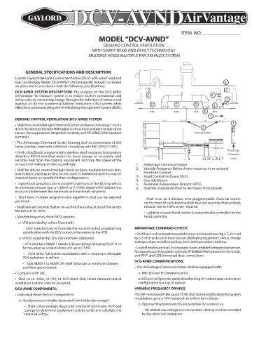
exhaust and makeup air fans accordingly. 1. AirVantage Command Center
• Shall be able to control multiple hood sections, multiple exhaust fans, 2. Variable Frequency Drives shown mounted in an optional
and multiple makeup air fans on one system. Additional systems may be Hood End Cabinet
required based on specific kitchen configurations. 3. Hood Control Enclosure (HCE)
4. Override Button
• Upon hood activation, the controller(s) will turn on the DCV system to 5. Resistance Temperature Detector (RTD)
its minimum exhaust rate; a 4-20mA or 2-10Vdc signal will modulate the 6. SmartAir Variable Air Volume Terminal Unit (optional)
exhaust rate between the minimum and maximum set points.
• Shall have multiple programmable algorithms that can be selected - Shall have an individual time programmable Override button
per hood. on the front of each hood section that will override that section’s
• Shall have an Override Button on each kitchen exhaust hood that ramps exhaust rate to 100% when required.
the exhaust to 100%. - Lighting on each hood section is automatically controlled by the
• Variable frequency drive (VFD) options: hood controller.
o VFD provided by others (Standard):
- DCV manufacturer will provide the recommended programming AIRVANTAGE COMMAND CENTER:
specification with the DCV output information to the VFD. • Shall have wall or hood-mounted control enclosure housing a 7-inch tall
o VFD(s) supplied by DCV manufacturer (Optional): by 4.3-inch wide color touchscreen displaying equipment status, energy
savings values, troubleshooting, and communications options.
- VFD shall be a NEMA 1 rated enclosure design allowing the VFD to
be mounted as a stand-alone unit up to 75 HP. • Control enclosure shall incorporate: room ambient temperature sensor,
fire suppression integration controls, VFD/BMS/VAV connection terminals,
- Shall allow full system modulation with a maximum allowable and Wi-Fi and USB download data connections.
70% reduction in airflow.
DCV-AVND COMMUNICATIONS:
- Type NEMA 1 or NEMA 3R rated forced air or vented enclosures
available upon request. • The AirVantage Command Center shall be equipped with:
• Complies with IMC. o BACnet over IP communication.
• Shall be UL 508A, UL 710, UL 873 listed. Only Listed demand control o USB port will provide quick downloading of runtime data and system
ventilation systems shall be accepted. configuration backup or upload.
DCV-AVND COMPONENTS: VARIABLE FREQUENCY DRIVE(S):
• Individual Hood Section Components: • NEMA 1 enclosed VFD(s) up to 75 HP, shall be installed to allow full system
modulation up to a 70% reduction in airflow from design.
o Hood process controller (accessed from inside the canopy)
- Shall utilize strategically placed canopy RTD(s) inside the hood o Optional: Engineered enclosures available for outdoor use.
canopy to determine equipment activity levels and calculate the - All related low voltage communication cabling shall be provided
required airflow. by the electrical contractor.