Page 92 - Gaylord Blue Book 2021
P. 92

GPC            -7000


                                                                            GPC          -6000-D


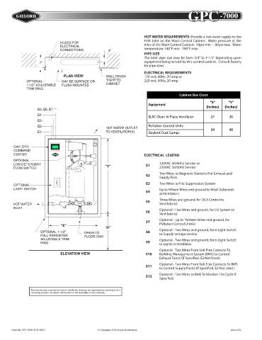
                                                                    HOT WATER REQUIREMENTS: Provide a hot water supply to the
                                                                    H.W. Inlet on the Wash Control Cabinet.  Water pressure at the
                                                                    inlet of the Wash Control Cabinet:  40psi min. – 80psi max.  Water
                                                             HOT  WATER  REQUIREMENTS
                                                                    temperature: 140°F min - 180°F max.
                                                              Equipment PIPE SIZE  Temp (°F)  Pressure (PSI)
                                                                    The Inlet pipe size may be from 3/4” to 1-1/4” depending upon
                                                              Water Wash Ventilator or  140 min.  40 min.
                                                                    equipment being served by this control cabinet.  Consult factory
                                                              Water Wash Ventilator w/ UV  180 max.  80 max.
                                                                    for pipe sizes.
                                                              Water Wash Ventilator w/ UV  140 min.  60 min.
                                                              and Pollution Control  180 max.  80 max.
                                                                    ELECTRICAL REQUIREMENTS
                                                                    120 volt, 60Hz, 20 amp or  30 min.
                                                                                  140 min.
                                                              Pollution Control Units  180 max.  80 max.
                                                                    220 volt, 50Hz, 20 amp
                                                                                  140 min.   40 min.
                                                              Gaylord Duct Sumps
                                                                                  180 max.  80 max.
                                                             PIPE SIZE               Cabinet Size Chart
                                                             The Inlet pipe size may be from 3/4” to 1-1/2” depending upon
                                                                                                   “X”
                                                             equipment being served by this control cabinet.  Consult factory   “Y”
                                                                      Equipment
                                                             for pipe sizes.                     (Inches)  (Inches)
                                                             ELECTRICAL REQUIREMENTS
                                                             120 volt, 60Hz, 20 amp Non-Interrupted Service or  24  36
                                                                      ELXC Clean In Place Ventilator
                                                             220 volt, 50Hz, 20 amp Non-Interrupted Service
                                                                          CABINET SIZE CART
                                                                      Pollution Control Units
                                                   HOT WATER OUTLET                                34       48
                                                   TO VENTILATOR(S)  NUMBER          ”X”       “Y”
                                                                      OF Gaylord Duct Sumps
                                                                   SEQUENCES        Inches    Inches
                                                              1-5 - Pipe Size = 1¼” Max.
       GAYLORD                                                1-4 - Pipe Size = 1½” Max.  34   48
       COMMAND
       CENTER                                                 5 - Pipe Size = 1½” Max.  40     48
                                                                    ELECTRICAL  LEGEND
       OPTIONAL                                              NOTES:
                                                                           120VAC 50/60Hz Service or
       LOW DETERGENT                                          A.  Consult Factory for Cabinets with more than 5 Sequences
                                                                     E1
                                                                           220VAC 50/60Hz Service
       FLOW SWITCH                                            B.  Add 6” to the “X” Dimension if Cold Water Mist is added.
                                                                 Consult Factory for Cold Water Mist information.
                                                                           Two Wires to Magnetic Starter(s) For Exhaust and
                                                                     E2
                                                             ELECTRICAL  LEGEND Supply Fans
                                                                           Two Wires to Fire Suppression System
                                                                     E3
                                                                   120VAC 50/60Hz Non-Interrupted Service or
       OPTIONAL                                               E1   220VAC 50/60Hz Non-Interrupted Service
       LIGHT SWITCH                                                  E4    Up to Fifteen Wires and ground to Wash Solenoids
                                                                           at Ventilators
                                                              E2   Two Wires to Magnetic Starter(s) For Exhaust and
                                                                   Supply Fans
         H.W. INLET                                           E3   Two Wires to Fire Suppression System
                                                                           Three Wires and ground, for DCA Control to
                                                                     E5
       HOT WATER                                                           Ventilator(s)
       INLET                                                       Five Wires and ground to the First Ventilator and
                                                                           Optional - Five Wires and ground, for UV System to
                                                              E4   them Five Wires from Each Ventilator Group to the
                                                                     E6
                                                                   Next Ventilator Group
                                                                           Ventilator(s)
                                                              E5   Two Wires and ground, for “Autostart” to Ventilator(s)
                                                                           Optional - Up to Thirteen Wires and ground, for
                                                 18”                 E7
                                                                           Pollution Control Unit(s)
                                                                   Optional - Five Wires and ground, for UV System to
                                        DRAIN TO  30”         E6   Ventilator(s)
                                        FLOOR SINK                         Optional - Two Wires and ground, from Light Switch
                                                                     E8
                                        DRAIN TO              E7   Optional - Up to Thirteen Wires and ground, for
                                                                           to Supply voltage service.
                                        FLOOR SINK                 Pollution Control Unit(s)
                                                                           Optional - Two Wires and ground, from Light Switch
                                                                     E9
                                                                   Optional - Two Wires and ground, from Light Switch
                                                              E8           to Lights in Ventilator.
                             ELEVATION VIEW                        to Supply voltage service.
                                                                           Optional - Two Wires From Volt Free Contacts To
                                                                   Optional - Two Wires and ground, from Light Switch
                             ELEVATION VIEW                   E9   to Lights in Ventilator.
                                                                     E10
                                                                           Building Management System (BMS) to Control
                                                                           Exhaust Fan(s) (If Specified, E2 Not Used.)
                                                                   Optional - Two Wires From Volt Free Contacts To
                                                              E10  Building Management System (BMS) to Control
                                                                           Optional - Two Wires From Volt Free Contacts To BMS
                                                                     E11
                                                                   Exhaust Fan(s) (If Speci ed, E2 Not Used.)
                 The manufacturer reserves the right to modify the materials and specifications resulting from a   to Control Supply Fan(s) (If Specified, E2 Not Used.)
                 continuing program of product improvement or the availability of new materials.
                                                              E11  Optional - Two Wires From Volt Free Contacts To BMS
                                                                           Optional - Two Wires to BMS To Monitor Fire Cycle If
                                                                   to Control Supply Fan(s) (If Speci ed, E2 Not Used.)
                                                                     E12
                                                                           Specified.
                                                                   Optional - Two Wires to BMS To Monitor Fire Cycle If
                                                              E12
                                                                   Speci ed.
               The manufacturer reserves the right to modify the materials and specifications resulting from a
               continuing program of product improvement or the availability of new materials.
       Form No. GPC-6000-D 0410-20233     © Copyright 2010, Gaylord Industries                  Litho USA
      Form No. GPC-7000 1018-20371             © Copyright 2018, Gaylord Industries                          Litho USA
   87   88   89   90   91   92   93   94   95   96   97