
Page 89 - Gaylord Blue Book 2021
P. 89
CUV
-1000
MODEL “CUV-1000” ITEM NO. _______________
CONTROL CABINET FOR VENTILATORS
GENERAL SPECIFICATIONS
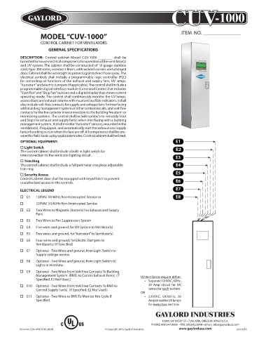
DESCRIPTION: Control cabinet Model CUV-1000-________ shall be
furnished to house electrical components for operation of the ventilator(s)
and UV system. The cabinet shall be constructed of 18 gauge stainless
steel, type 300 series, number 4 finish, with welded corners and a hinged
door. Cabinet shall be watertight to protect against direct hose spray. The
electrical controls shall include a programmable logic controller (PLC)
for controlling all functions of the exhaust and supply fans, UV lamps,
“Autostart” and electric dampers (if applicable). The control shall include a
programmable digital interface module (Command Center) that includes
“Start Fan” and “Stop Fan” buttons and a digital display that shows current
operating mode. The control shall continuously monitor the UV lamps,
access doors and exhaust volume with visual and audible indicators. It shall
also include volt-free contacts for supply and exhaust fans for interfacing
with building management system or other control circuits, and volt-free
contacts for the fire cycle for interconnection to the building fire alarm or
monitoring systems. The control shall include contacts to remotely Start
and Stop the exhaust and supply fan(s) when interfacing with a building
management system. It shall monitor “Autostart” sensors, mounted in the
ventilator(s), if equipped, and automatically start the exhaust and supply
fan(s) if cooking occurs when the fans are off. All components shall be pre-
wired for field hook-up by applicable trades. Control cabinet shall be listed.
OPTIONAL EQUIPMENT: E1
o Light Switch
The control cabinet shall include a built-in light switch for E2
interconnection to the ventilator lighting circuit. E3
o Trim Ring
The control cabinet shall include a full perimeter one piece adjustable E4
trim ring.
o Security Access E5
Control cabinet door shall be equipped with keyed latch to prevent
unauthorized access to the controls. E6
ELECTRICAL LEGEND E7
o E1 120VAC 50/60Hz Non-Interrupted Service or E8
o 220VAC 50/60Hz Non-Interrupted Service
o E2 Two Wires to Magnetic Starter(s) For Exhaust and Supply
Fans
o E3 Two Wires to Fire Suppression System
o E4 Five wires and ground, for UV System to Ventilator(s)
o E5 Two wires and ground, for “Autostart” to Ventilator(s)
o E6 Four wires and ground, for Electric Dampers to
Ventilator(s) (If Specified)
o E7 Optional - Two Wires and ground, from Light Switch to
Supply voltage service.
o E8 Optional - Two Wires and ground, from Light Switch to
Lights in Ventilator.
o E9 Optional - Two Wires From Volt Free Contacts To Building
Management System (BMS) to Control Exhaust Fan(s) (If UV Ventilators require either:
Specified, E2 Not Used.) • Separate 120VAC, 60Hz,
o E10 Optional - Two Wires From Volt Free Contacts To BMS to 20 Amp circuit for UV
Control Supply Fan(s) (If Specified, E2 Not Used.) lamps for each section
OR
o E11 Optional - Two Wires to BMS To Monitor Fire Cycle If • 220VAC, 50/60Hz, 20
Specified. Amp circuit for UV lamps
for every two sections
GAYLORD INDUSTRIES
10900 SW AVERY ST • TUALATIN, OREGON 97062 U.S.A.
C US PHONE: 800.547.9696 • FAX: 503.692.6048 • email: info@gaylordusa.com
Form No. CUV-1000 0310-20201 © Copyright 2010, Gaylord Industries www.gaylordusa.com Litho USA